Written by Dr. Koen Vervaeke
Summary
We report on a method to measure a noise-free magnetic field distribution of rotary encoder sensor magnets, based on Magcam’s established 3-axis magnetic field camera technology. This method involves measuring the 3-axis magnetic field distribution in a 2D plane at close distance above the magnet and extrapolating this field distribution into a 3D volume using a patented ‘Distance Filter’ algorithm that yields virtually noise-free data at larger distances. This powerful method allows to evaluate the magnetic field distribution and the magnet’s intrinsic angular error, with a resolution better than the measurement resolution of the originally measured plane.
Background, Motivation, and Objective
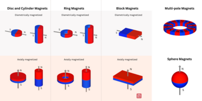
A method is presented for magnetically characterizing 2-pole rotary encoder magnets, which are widely used in angular encoders in e.g. electric motors and rotary positioning systems. The method uses a proprietary ‘Distance Filter’ algorithm, which allows to extrapolate a magnetic field distribution recorded at one certain (close) distance above a magnet or magnet assembly to another (larger) distance in a very fast way and with a strong suppression of measurement noise. This allows very fast and at the same time highly accurate measurements, making the method suitable for production quality control.
The Distance Filter Method
The Distance Filter algorithm is used in combination with Magcam’s magnetic field camera systems. When the extrapolation is in the direction away from the magnet, there is a strong suppression of noise, resulting in µTesla magnetic field resolutions. This makes the Distance Filter algorithm very powerful for determining magnetic field distributions far away from a magnet, since a direct measurement at the farther distance would suffer from a poorer signal-to-noise ratio.
For accurate results with the Distance Filter, the recorded magnetic field distribution must contain the full magnetic field of the measured magnet or magnet assembly, meaning that at all edges of the measured magnetic field image the magnetic field should be monotonically decreasing towards zero when going outwards towards the image edges. In practice, this means that a sufficiently large area should be measured, including extra space around the magnet.
Results
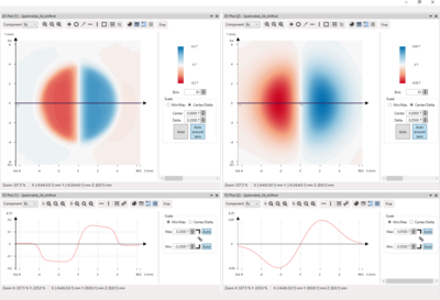
Consider a cylindrical axially magnetized 2-pole rotary encoder magnet, with the cylindrical symmetry axis pointing in the Z direction. The original measurement is in the XY plane at a certain height Z0 above the magnet surface. The magnetic field distribution at a different height Z1 is obtained by the Distance Filter method by supplying one single input parameter Delta, namely the distance between the original measurement plane and the desired plane: Delta = Z1 - Z0. When Delta > 0 the extrapolation takes place in the direction away from the magnet. When Delta < 0, the extrapolation is in the direction towards the sample. When Delta = 0 the original data is retained.
Figure 1 shows the measured Bz magnetic field distribution and cross section along the X direction at Z0 = 0.3mm (left) and Distance Filter result at Z1 = 2mm (right). Hereby the value for Delta is: Delta = 2mm - 0.3mm = 1.7mm.
Analyzing Bxy and azimuthal angle error in 2-pole rotary encoder magnets
In a typical end application a Bx,By sensor is positioned on the symmetry axis of the rotary encoder magnet at a certain distance from the magnet surface, which is typically several mm. At such distance the Bxy magnetic field is typically of the order of 50mT. The Bx,By sensor then measures Bx and By and from those calculates the in-plane angle of the magnetic field using atan2(By,Bx). Due to inhomogeneities of the magnetic field distribution, there is a certain error on this measured angle value. During quality control on such magnets, this angle error needs to be determined with high accuracy, typically in the order of 0.1° or better. By using a magnetic field camera in combination with the Distance Filter this can be achieved in a superior way as shown below.
A magnetic field distribution measurement directly at the working distance of the Bx,By sensor in the above application would result in a poorer signal-to-noise ratio than a measurement very close to the magnet (typically 0.3-0.5mm). The Distance Filter makes it possible to ‘preserve’ the signal-to-noise ratio at close distances to remote distances, resulting in virtually noise-free magnetic field distributions.
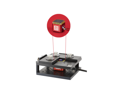
The 3D magnetic field distribution is measured at a close distance above the magnet surface using a Magcam MiniCube 3D magnetic field camera (see Fig. 2).
As mentioned higher, the relevant magnetic field components for this application are the in-plane (Bxy) magnetic field and the in-plane direction (azimuthal angle) of the field in a region in the center of the magnet. These components can be analyzed as explained below.
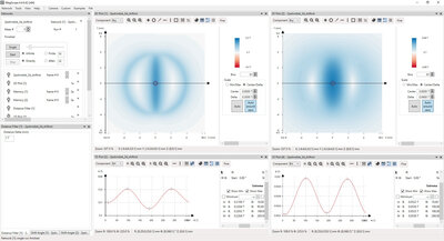
Bxy component and azimuthal angle
The Bxy component is readily obtained from the Bx and By components of the magnetic field (Fig. 3). A circle is interpolated centered on the magnet center and with a certain radius, taken to be 0.25mm in this example, typically determined by the tolerance region where the Bx,By sensor will be located in the end application. In the obtained line plot, the maximum and minimum values can be automatically detected, which can be directly used in a pass/fail test to check if they are within the tolerance window.
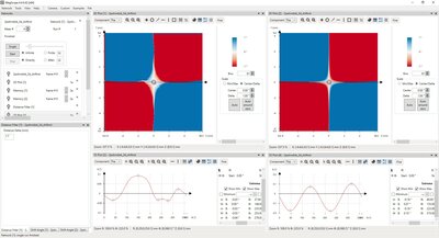
The second important quantity of the magnetic field distribution is the in-plane direction (azimuthal angle) distribution of the magnetic field. This quantity is also readily calculated from the Bx and By components of the magnetic field by using atan2(By,Bx). By analyzing the extreme values of the azimuthal angle on the same circle section as before, the angle error is directly obtained, as shown in Fig. 4.